How To Open Pcb File On Phone
Do you want to make a PCB board without files and just have the complete product ? Take it to us, we make it for you.
How did we do that ? I show you simple now.
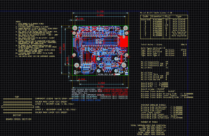
This following thing we did, called PCB copy, also called PCB clone and PCB reverse engineering.
The first thing after we got it, is take two photos of two sides and record all the types of components, also the position, especially the position of diode and tiode.

The second thing is take down all the components and tins in PAD holes. Clean the PCB board and put it in scanner until get a clear image. Use the waterproof abrasive paper polish the top layer and put it in scanner again. Using PHOTOSHOP and scan it with colorful.
How To Open Pcb File On Phone Number
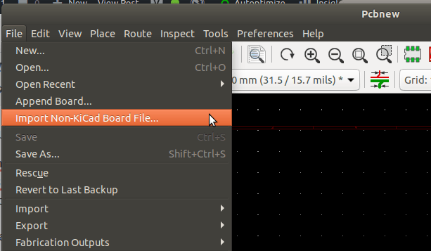
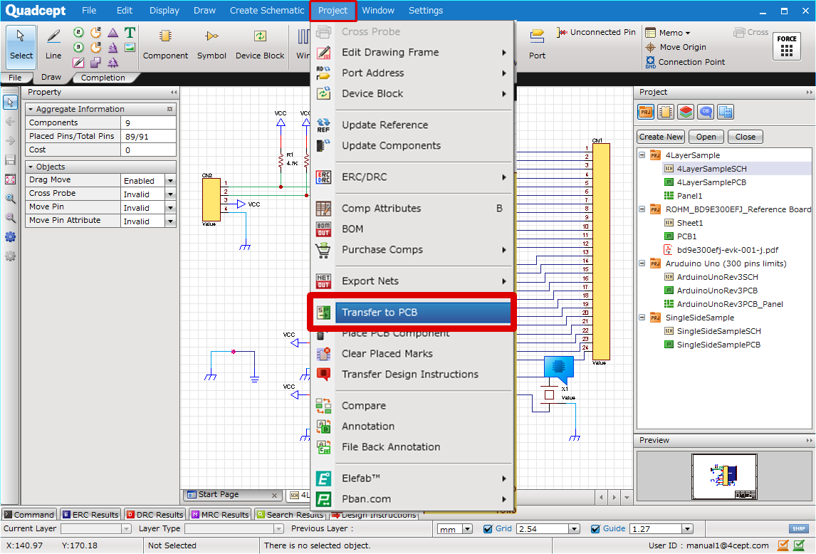
This is a very powerful Schematic and PCB layout tool for electronic Engineer. It is very easy to use. Coming version will add the SPICE features as well as the 3D model. This tool is target for single user, so all the things such as Schematic, PCB layout, SPICE model, 3D models are all combined into a single project file '.prj' in ZIP file form. Once connected, open a Finder window at any time and click iPhone (or whatever you named your device) to access its photos and other files. How to Transfer Photos From Your iPhone to a PC Moving pictures from an iPhone to a PC isn't too difficult, but there are a couple of additional steps. Create Gerber Files in KiCad. From the PCB Editor in KiCad you can create Gerber files by going to the File menu and selecting Plot A window will appear. Click on the Plot button to create the Gerber files. To create Drill files, click on Generate Drill Files to open the Drill File dialog. Then click the button Generate Drill File. PCB file openers, viewers, etc. These apps are known to open certain types of PCB files. Remember, different programs may use PCB files for different purposes, so you may need to try out a few of them to be able to open your specific file. This videos shows you how to open a temp file. Please remember to Subscribe and Comment.
To make the circuit more clear, we adjusted contrast and intensity through PHOTOSHOP. Finally it’s clear enough now.
Change the .BMP file to .PROTEL file and leading-in this two files. If the position of PAD and VIA is coincident, it means we did it very well. If there is any deviation, repeat the last step. Untill it’s coincident. It means we succeed now.
Change the .BMP file to POT PCB, and draw circuit, according the second step, draw the position of components.
Last step is testing, finish it and you succeed on it.
About JY Electronic®
JY Electronic® is the established leader in providing innovative and reliable PCB & PCBA solutions for the electronic design industry. With over 20 years of experience in supplying high quality, on-time PCB & PCBA prototypes and mass production, JY Electronic is committed to improving production process for the design engineer from quote to delivery.
JY Electronic provides unparalleled customer service and leads the industry with a real On-Time Guarantee that is the first of its kind. For more information about JY's innovative PCB & PCBA solutions, or to learn more about quote and ordering process, please visitwww.JYcircuitboard.com

- » Previous: Magnet pcb sensor operating Instructions
- » next: PCB heatbed for 3D printer
- The Air Quality Sensor Board
his PCBA was made for one of our American customers. This customer is in the smart home industry. The products produced by our company include circuit boards in ...
- Protective circuit device of small controller
Products Purpose: Protective circuit device of small controller. Working principle: Convert the volts higher than the used voltage to the volts that can meet ...
- Thermodynamics and PCB design
When PCB design is becoming smaller, thinner, and PCB products with a large amount of accumulation ability, we must take the heat factor into consideration. You ...
- What are PCB board materials?
With the continuous expansion of PCB market capacity, the demand of PCB board is also increasing. How to select the most suitable plate for proofing has become ...
- 4 PCB+4 PCBA projects
We are working with Australian customers on 4 PCB projects and 4 PCBA projects. These items are used for electrical equipment testing, safety testing, preventio ...
- Pure Resistance Cirtuits
What is the pure resistance circuits?In AC circuit, resistance (R), inductance (L) and capacitance (C) are three basic circuit components. If there is only one ...

Open Pcb File Ppt

Pcb File Open
PCB Prototype
PCBAStore offers rapid PCB prototyping services for quick-turn PCB at high quality and low cost that no only makes your PCBs quick, but also makes your job right as well as cost-effective.
Read more...Layers: 1-64
Quantity: 1-100 pcs.
Quality: IPC Class 2
Build time: 1-10 days
Material: FR-4 / PI /
ALU / Ceramic /
PTFE etc.PCB Fabrication
We can fabricate Buried & Blind holes, laser drilled microvias boards (HDI), heavy copper up to 30 oz, via-in-pad, microwave & RF boards, Rigid-flex board and others with our state-of-the-art PCB equipments.
Read more...Layers: 1-40
Quantity: 1-1million pcs.
Quality: IPC Class 2-3
Build time: 2 days-4 weeks
Material: FR-4 / PI /
Aluminum / Ceramic /
PTFE etc.PCB Assembly
We have advanced capabilities for SMT assembly, through-hole and mixed technology PCB assemblies to enable us meet all customers' PCBA needs under one roof in an inexpensive way.
Read more...Type:SMT and THT Assembly
Quantity: 1-1million pcs.
Quality: IPC Class 2-3
Build time: 1-10 days
Fulfillment: Turnkey or
kittedPCB Layout
We possess a professional PCB layout team with average design experience over 10 years and full experienced of design. They master various EAD software such Allegro, POWER PCB, Altium Designer, AUTO CAD and CAM350 etc.
Read more...layers: 1-40
Max PIN count: 69000+
Trace/Space: 2.5/2.5mil
Min Via: 6mil (HDI 4mil)
Max BGAs in a single PCB:
62